Manual
Introduction
tes•LAX is a CAN bus Explorer and visualization tool. While it may be useful for many vehicles, tes•LAX was specifically designed with a specific popular Electric vehicle in mind.
This manual is intended to help you get the most out of tes•LAX.
Support
tes•LAX is a free-time effort of a single developer. Limited support inquiries can be sent using the issues tracker here: https://github.com/tesLAXApp/tesLAX/issues
 Presets
Preset List
A “preset” within tes•LAX is the combination of the list of signals and the pages/gauges configured. Different vehicles may have different signals, and this allows you to quickly switch between configurations.
tes•LAX comes pre-configured with several presets. The “extended release” feature set allows editing of these presets. tes•LAX releases may be bundled with new versions of the signal database. You may be prompted to update their database. To do so, you will need to visit the Preset list.
The bundled 3/Y/Plaid presets have a signal list that is maintained at https://github.com/joshwardell/model3dbc by Josh Wardell with contributions from the community. Given that the manufacturer changes messages and signals without notice, you may wish to import a more recent DBC. DBC import is part of the “Extra Strength” feature set. Currently, there is no one maintaining an S and X database in the same manner. The app provides some signals from various community sources on the web and may be out of date. If you have any suggestions for improving this preset, please submit them using the issue tracker here: https://github.com/tesLAXApp/tesLAX/issues
You may see the following icons next to presets in the list:
 This means this present originally came bundled with tes•LAX but has been since been edited by the user.
 This means that the current version of tes•LAX contains an updated version of this preset. To update, select the preset from the list and tap the
  button. Then select “Restore Full Preset to Bundled Version” Note that this will erase the existing signal database and configured gauges and restore the new version as it is bundled with the application. If you previously edited this preset, then those changes will be lost.
 This means that the Preset used to be bundled with tes•LAX but is no longer included or updated. You can chose to keep the preset, or delete it. Since the preset is no longer bundled with tes•LAX, it will be lost and cannot be restored.
When the app contains a bundled preset that is not currently loaded into your active list of presets, it will appear at the bottom of this list under “Available Bundled Presets”. You can opt to add them to your active list or hide them if you do not wish to use it. If you have any hidden presets, you can restore them again using the menu item “Show hidden presets”. This will restore any bundled presets that you have hidden in the “Available Bundled Presets” section.
tes•LAX is under active development and while every effort to maintain your custom configurations will be made, some updates may require a database reset.
Tapping an item in the Preset list will activate the preset. A check mark appears to indicate the active preset. The active preset cannot be deleted.
Tapping the button will bring up the Preset Details screen for the selected preset.
Preset Details
By tapping the button in the preset list, you can see the details of the preset.
You can assign names to numeric bus identifiers in this screen. This is used for multi-bus data sources. See the “Advanced: Multiple Buses” section below for more information.
The Preset Details screen allows the following functions if a preset is bundled with the app:
- Restore the complete preset (including messages, signals, and configured gauges) from the default bundled version.
- Restore only the signal database for this preset.
- Restore only the configured gauges.
The “Extra Strength” feature set provides these additonal features:
- Edit the preset name, icon, and description by tapping the Edit button in the upper right.
- Delete a preset
- Duplicate a preset
Location Augmentation Feature
The location augmentation feature allows a synthesized message with longitude/latitude data to be created using the iOS device’s internal GPS. To enable this feature, you must select the signals from your signal list that you wish to synthesize. The feature can be used in 2 modes:
- “Replace” will ignore any incoming message from the accessory or log file or accessory and insert new message based on the location information provided by the iOS device’s internal GPS.
- “When Not Present” will watch the data stream for the chosen signals/messages. If data is available from the CAN bus log or accessory, it will be passed along. If no data is seen from these singles for a short time, then tes•LAX will begin to synthesize the signal from the iOS device’s internal GPS.
 Note: it is recommended that you grant the app full access to location data (even when “not in use”). This will allow proper background access to the GPS. tes•LAX never collects metrics on this location information. Location information may be saved in CAN log files, but these files are fully under the ownership and control of the user and are never shared (unless explicitly shared by the user)
 The Signal Database
tes•LAX decodes CAN bus data by referring to the signal database. The signal database contains messages and signals and information how to decode them from the CAN bus data stream.
 Messages
A message is a group of signals. A message is a single transmission on the CAN bus, meaning that all signals within a message are sent/received at the same time.
- Messages are identified by a 11-bit number called the “Message ID”.
- The “Message Name” is used to help identify the message. It must be unique and cannot contain spaces.
- The “Message Size” is the number of bytes of the message. tes•LAX will discard messages that to not have the proper number of bytes.
- The “Transmitter” is a field used identify which device transmitted a message on the bus. Currently it is not used by tes•LAX.
- The “bus name” determines the bus on which this message is decoded when using a multi-bus accessory or log file playback with a file that has multiple bus information.
Signals
A signal contains the value of interest within the message.
-
The Display Name provides a user-friendly way of describing the signal.
-
The Signal Name is an identifier that does not contain spaces. This identifier is used elsewhere in tes•LAX, for example to associate a signal with a gauge.
-
The Message ID field associates a signal to the message and identifies which which message contains the value.
-
The Message Type is one of two values:
- Standard values are decoded from the bytes in a message stream.
- Calculated values are determined by executing a small bit of javascript.
-
The Signed/Unsigned field identifies how the bytes are encoded in the message. Signed values are encoded with two’s-complement.
-
Value Type determines how tes•LAX will display the signal. It is one of three values:
- Integer - the value is an integer (no decimal)
- Double is a number with a decimal point.
- Enumeration is a numeric signal that evaluates to a text value. For example 0=Yes and 1=No. The lookup for the value is defined in the “Enumeration Values” section.
-
The Scale identifies the minimum and maximum of the signal. This can be used to define the range of a gauge.
-
Location identifies where in the message the value is found. It also identifies wither the signal is big-endian or little-endian.
-
Factor/Offset determines how the signal is scaled and interpreted. The raw value is the message is multiplied by the factor and added to the offset.
-
Units Type determines the unit of measure for the signal. It can be multiple types:
- Constant means the unit is always the same, and is a text value defined in the Unit field.
- Alternate Signal means that the signal’s unit can change based on the value of another signal in the same message. This other signal is usually an enumeration. For example this alternate signal may be 0 for MPH and 1 for KPH. When selecting this type, the signal that contains the unit need to be selected.
- There are various other unit types, such as Celsius, Fahrenheit, Miles, Kilometers, etc. By selecting one of these types, tes•LAX will convert the units into the users preferred unit type based on the settings.
- Some unit types like Watt/Kilowatt will also scale based on the size of the value. When a signal with a watts unit grows past 1000w, it will scale to kilowatts.
-
The Enumeration Values section is for values defined as Enumeration and contains the numeric values and textual description. Some non-enumeration values may have a “Signal Not Available (SNA)” enumeration value but tes•LAX does not refer to this for values that are not enumerations.
-
Multiplexing is for multiplexed signals. If applicable the signal identifies the multiplexer within the same message. The multiplexer index identifies the value of the multiplexer when this signal is currently part of the message.
-
Script is for calculated signals. See the Advanced: JavaScript for Calculated Signals section for more information on how this works.
 Visualization and Gauges
The current visualization can be configured using the  menu in the upper right. The word “Gauge” and “Widget” my be used interchangeably.

- Edit Gauges and Layout lets you add, remove and configure pages and gauges.
- Flip View will reverse the screen horizontally for use in situations where you want to reflect the display off of another surface.
- The CAN Bus Cam menu item will activate the camera feature.
Also, some pages may have additional controls. For example:
- A page of gauges will have a Columns picker that lets you choose a one, two, three, or four column view, and a slider to configure the height of the gauges.
- The graph page will have an option that lets you reset the graph
- Other pages types may have other options specific to the page type.
Gauges and Layout
The Edit Gauges and Layout will bring up the list of pages for the current preset.
Note: that you must have purchased Extended Release or Extra Strength to edit or add new gauges and pages. Subsequent pages of gauges will also become active upon purchase.
Tapping the info circle next to the page will bring up the page-level settings for the selected page. This includes things like the name of the page and the icon shown in the tab. Some pages may have additional options.
If the page is configurable with a list of widgets or gauges, tapping anywhere else on the row will bring you to the list. You can then edit and reorder the individual widgets on the page. Not all pages have widgets or gauges.
From the page list, you can:
- Use the edit option in the upper right to reorder or remove pages.
- Use the add new option will let you add a new page. A list of available page types will be displayed.
- Tapping the info circle to edit the page-level settings. At a minimum, this includes the page name and icon, but some page types have more advanced options.
- Tapping anywhere else to bring up the list of widgets or gauges on the page. Not all page types have widgets and gauges. You can configure, remove, reorder, and add new gauges and widgets from this page.
 Pages
Pages
Page tabs will appear at the top of the main tes•LAX screen. (This can be optionally disabled in settings.) Each page has a corresponding icon. When a page is selected, the gauges for that page will be displayed in the active area. Note: gauges that are currently on pages other then the active page will also be evaluated. The total number of gauges across all pages should be considered when building a preset. Too many gauges may result in performance degradation. Furthermore, your data source (such as a Bluetooth accessory) may have insufficient bandwidth to provide all of the data, resulting in buffer overruns.
Note: tes•LAX comes with presets that contain multiple pages, but only the first page is available to users who have not purchased these extended features.
Gauge Page
A gauge page provides a grid or list of signal gauges and is the most commonly used page type.

For all gauges, there is a column span parameter which will allow the item to span multiple columns.
Static Text
A static text item is simply a label added to your visualization in the place of a gauge.
Signal Gauge
A signal gauge allows you to visualize a signal.
- The subtype parameter lets you choose a radial, linear, or numeric digital version of the gauge.
- For signals that are decimal, you can limit the number of decimal places
- Range lets you determine the maximum and minimum of the gauge
- Static will keep the maximum and minimum values as defined in the signal database.
- Lifetime Max/Min will use the maximum and minimum values as observed over the lifetime of the app.
- This Drive Max/Min will use the maximum and minimum values as observed during the session as defined by the last time an accessory or log file playback was started.
- Symmetric Range will center the origin of and make the maximum and minimum values the same (one positive and one negative)
Binary Message
The Binary Message visualization is part of the extra strength feature set. It will show the bits of the message a 8x8 matrix. You must select a message from the signal database.
Binary Signal
The Binary Signal visualization is part of the extra strength feature set. It is the same as the Binary Message visualization, but will highlight the bits of the selected signal in the context of the other bits of the message. You must select a signal from the database.
Signal Metrics
The signal metrics widget will show the maximum and minimum values for the selected signal (both lifetime and for the current drive session). It also lets you reset the the observed maximum and minimum values.
Acceleration
This widget accepts X/Y values and plots them in two axes. It is typically used for acceleration values.
Map Page
Note: that you must have purchased Extra Strength 2.0 to use the graph page.
A Map Page allows you to visualize longitude and latitude information on a map. You can also select another signal that will determine the color of the path drawn on the map.
Note: Some of the bundled presets may use longitude and latitude signals from a second bus. Single-bus data sources will not be able to provide this longitdue and latitudue information in such cases. If you intend to use this map page, make sure your data source provides the longitude and latitude signals necessary. Alternatively, you may be able to use the “Location Augmentation” feature of the preset to synthesize location messages from the phone’s internal GPS.

The “auto-zoom” option will attempt to scale the map view so that the entire rendered path is visible in the view port. Manually panning or zooming the map will disable this feature.
The History Buffer Size setting (found on the settings page) will determine how many previous locations are kept for a map page. After this number is reached, older locations may be discarded to prevent exhausting the device memory.
Graph Page
Note: that you must have purchased Extra Strength 2.0 to use the graph page.
A graph page will provide a line graph visualization of a group of chosen signals.
The graph widget lets you add up to 10 signals to the visualization.
At the current time, the graph is a fixed view port and does not support panning or zooming.
You can clear the graph using menu in the upper right.

Note: the History Buffer Size setting (in the settings app) will determine how many previous data points are kept for a graph series. After this number is reached, older data points may be discarded to prevent exhausting the device memory.
Drag Timer
Note: that you must have purchased Extra Strength 2.0 to use the graph page.
A drag timer page will time “0-60 mph” style time intervals. It requires a speed signal, an odometer signal (to track distance), and brake and accelerator signals to determine the start of the run. This page also shows lateral and longitudinal acceleration.
tes•LAX’s default presets include a large number of signals and depending on your data source there may be a large number of messages and signals being processed at any given time. This can result in variances or inaccuracies. If you are concerned with the accuracy of the drag timer, it is recommended that you create a preset with only the drag timer page and no other signals. The speed of your iOS device can also affect the rate at which data is processed.
Even still the drag timers is intended for informational purposes only and not precise timing, as there are many reasons why CAN bus messages may be delayed. As always when using tes•LAX, and also when using the drag timer, please do so safely and responsibly and obey all traffic laws and safety concerns.
Note: Some of the bundled presets may use acceleration signals from a second bus. Single-bus data sources will not be able to provide this acceleration information in such cases. This will result in a non-functional lateral and longitudinal acceleration visualization.

To use the drag timer:
- Tap on the “Begin” button. The drag timer will wait for you to come to a complete stop with the accelerator signal at zero.
- Once the Drag Timer has determined that the data indicates a full stop, the Timer will remind you to safely begin your timing run.
- When the Timer determines that the pedal has been depressed and the brake release, the timing run will begin
- The timing run will continue until all timers are completed, a braking condition is detected, or the speed falls from 20% of the peak value.
- You can stop the run manually with the STOP button.
- When the run is complete the buttons will change to let you start a new run, or share the results as an image.
The following page level configurations are available for the drag timer:
- Vehicle Speed - the signal that provides the vehicle speed to the drag timer. Must be a signal in MPH or KPH. Will assume KPH if signal is not properly configured.
- Odometer - this signal is used to determine the distance traveled during an interval.
- Accel Pedal Position and Brake Pedal Position - these signals are used to determine the start/stop of a run. The timer will reset when Accel Pedal is zero and the brake engaged, and the timer will start when Accel Pedal goes above zero. If the brake pedal is pressed (like when doing a cheetah launch) the Accel Pedal signal will not start the timer until the brake signal is released (goes to zero).
- Lateral and Longitudinal Acceleration - these signals are to populate the acceleration widget in the upper right. Note that these signals, in many of the presets, are on a second bus and may require a multi-bus data source.
Matrix Page
Note: that you must have purchased Extra Strength 2.0 to use the graph page.
The matrix page is intended to show small cells of similar data, such as the voltages of battery cells. It can accept data from multiple signals. Each cell can be sourced directly from a signal. This page also supports signals with maximum and minimum values sources from a “index and value pair”.

When an update is received for one of the signals, the cell will flash. The color is on a scale of red to green, where red = minimum and green = maximum. This color will fade to gray scale after a short time, indicating that the signal was not refreshed recently. When grayscale, a darker color indicates closer to the minimum while a lighter color indicates closer to the maximum.
Flags in the corner of a cell indicate that the maximum or minimum value.
Note that it is possible that updates to signals come in at different times (not all at once) and updates may be “rolling” depending on your source signal. This means that maximum and minimum values may jump around as it is possible that a large change has occurred between the time the first cells are updated and the current cells are updated.
The following page level configurations are available for the matrix page:
- Max Signal - a signal that provides the maximum value across all individual signals shown in the matrix.
- Min Signal - a signal that provides the minimum value across all individual signals shown int he matrix.
- Max Index - a signal that provides the index number of the cell for which the Max Signal is currently indicating.
- Min Index - a signal that provides the index number of the cell for which the Min Signal is currently indicating.
Web Tab
Note: that you must have purchased Extra Strength 2.0 to use the graph page.
A web tab allows you to load a web page within a tab, alongside your other visualization tabs. This feature is intended for loading the configuration/status pages from connected accessories, but can be used to load any web page.

The following page level configurations are available for the matrix page:
- URL - the default URL to load into the web browser
CAN Bus Cam
The CAN Bus Cam feature allows you to record video while overlaying the top four gauges from your current preset.
tes•LAX will request access to your camera, microphone, and photo library for this feature. If granted, tes•LAX only uses these permissions to record audio and video at the user’s request, and save the resulting video to the user’s camera roll.
- This feature is CPU intensive and may lag or drop frames and audio if your device can’t keep up.
- Upon pressing the “record” button, the camera will lock to the current orientation (portrait or landscape)
- Upon completing your recording, the video will save to your camera roll.
- When recording is complete, press the icon to return to the main screen. This icon will not appear during recording.
 Connecting to Accessories
tes•LAX can connect to some OBD-2 accessories to show live CAN bus data from your vehicle. Not all accessories are compatible and supported. Additional wiring, and installation is necessary. Damage done to your vehicle may not be covered by vehicle warranty. Proceed at your own risk.
An important note about security
Many accessories allow you to monitor AND also transmit data into the CAN bus. tes•LAX is not designed to transmit to the CAN bus and only uses these accessories for passive monitoring. That said, the ability to transmit data to a CAN bus is a potential security concern. A malicious third party could send many possible commands to take control of the vehicle, unlock doors, pop the trunk, etc. Some accessories are designed to be inherently read only and would only pose a privacy risk as they cannot transmit on the CAN bus.
Some accessories have security that prevents unauthenticated parties from connecting. Some accessories can be secured with a password.
Other accessories have an initial pairing process on power-up. While these may be secure during active use, these devices should not be left connected to your car because it is possible to “wake up” a sleeping vehicle (by touching a door handle, perhaps). This could power up the accessory in the initial pairing state, allowing a window for a malicious third party to issue commands.
Many accessories have no security at all. Please assess the risks of your accessory and setup and take precautions to keep your vehicle secure. Again, any use of these accessories is at your own discretion and at your own risk.
Please consult your accessory manual or manufacturer to learn if your accessory can be secured before using it with tes•LAX.
Serial AT- and ST-command Set Accessories
tes•LAX supports connectivity to WiFi and BLE based accessories that use the AT- or ST- command sets. It is recommended that you use an accessory that supports the ST- command set, as it supports filtering. ELM327-based AT- command set accessories do not support filtering and also do not have sufficient performance. Use of such accessories may work with significant buffer overruns and lost packets.
Given the number of accessories in the marketplace, tes•LAX can not guarantee compatibility with every accessory. Please test your accessory using the free feature set before deciding to purchase additional features.
Bluetooth Classic
tes•LAX supports connectivity to the OBDLink MX+ accessory. This is currently the only supported “Bluetooth classic” accessory.
You must first pair and connect to the accessory in the iOS standard Settings app first. Then come into tes•LAX and select “Accessories” from the upper left menu. Any connected accessories will be shown. Tap the accessory to begin a connection.
You can also select connect to first available if you wish tes•LAX to connect to any accessory when it is (or becomes) available for connection.
Bluetooth Low Energy
tes•LAX supports some Bluetooth low energy accessories. tes•LAX will ask permission to access Bluetooth. This is only used for the purpose of connecting to a bluetooth low energy accessory.
Given the number of accessories in the marketplace, tes•LAX can not guarantee compatibility with every accessory.
For advanced users, you can configure a custom service UUID and characteristic UUIDs in the settings page to account for a serial accessory that exposes itself over BLE using custom identifiers.
WiFi Accessories
tes•LAX supports connectivity to WiFi based accessories that use the AT- or ST- command sets. It is recommended that you use an accessory that supports the ST- command set, as it supports filtering. ELM327-based AT- command set accessories do not support filtering and also do not have sufficient performance. Use of such accessories may work with significant buffer overruns and lost packets.
Given the number of accessories in the marketplace, tes•LAX can not guarantee compatibility with every accessory. Please test your accessory using the free feature set before deciding to purchase additional features.
Also, note that some WiFi accessories use and open network which is not password protected or encrypted. This can pose a security risk, as some accessories allow writing to the CAN bus as well. We do not recommend using accessories with open networks. Please consult your accessory manual or manufacturer to learn if your accessory can be secured before using it with tes•LAX.
Panda OBD-2 Interface
The Panda OBD-2 Interface for Comma.ai is supported for advanced users. The Panda is not recommended for novice users. Some notes about the Panda:
- IMPORTANT: Sometime around August 2020, Comma.ai decided to discontinue WiFi support from the Panda White. This makes it unsuitable for use with iOS devices and tes•LAX. Advanced users may wish to re-flash their Panda with an older firmware that maintains WiFi support for use with tes•LAX. Version v1.5.2-DEV has been confirmed to work (see https://github.com/commaai/panda-artifacts) as later versions may have WiFi disabled.
- There are other accessories that use the same protocol, such as Josh Wardell’s CANServer product. If your specific accessory uses a different IP address, you may need to change the accessory settings to before tapping connect. CANServer also supports an extended protocol with filtering. tes•LAX also supports this protocol when used with accessories that support the additional commands.
- You must join the Panda’s WiFi network in secure mode prior to connecting in tes•LAX. This means that you will require the WiFi password for your Panda. The only way to retrieve the password from the Panda is over USB using the Python API. This requires a special USB device called a “Panda Paw” or a non-standard USB-A to USB-A cable without the 5v pin connected.
- The Panda supports up to 3 buses. You can select which bus you would like delivered to tes•LAX. If you select ‘all’ then every message from any CAN bus will be delivered to tes•LAX. Typical OBD-2 harnesses usually use the Panda’s 1st CAN Bus channel (physical bus index = 0).
- Enabling the “Passive Mode” toggle before initiating a panda connection will put the app into a “listen only” mode. This is for advanced users that want to stream raw UDP data in Panda format to tes•LAX. tes•LAX will not send the keep-alive packets or provision filters in this mode.
 File Operations
The “Open File” option in the upper left menu will allow you to select a log file from your iCloud drive or local device. tes•LAX supports the following file types:
- TXT file - this is a standard log file format of HEX CAN bus data. Each line is a a hexadecimal message. The first 3 hexadecimal characters are the message ID, and the remaining hexadecimal characters are the content of the message. It is not timestamped, so tes•LAX will replay a TXT log file at a constant rate.
- ASC file - this is a typical CAN bus file format. It contains additional information, but tes•LAX only refers to the timestamp, message ID, and message bytes. tes•LAX will refer to the timestamp when determining when to deliver the next message to the visualization.
- DBC file - import a DBC file into your signal database. See the DBC File Import section for more information
Note about file locations
There may be two tes•LAX folders on your device. One in iCloud and “On My Device”. tes•LAX will prefer the iCloud folder for log file generation and CSV convert, if available. If there is an issue accessing the iCloud Drive, tes•LAX will fallback to the “On My Device” folder. When debug logging is enabled, debugging console log files are only stored “On My Device”.
- To find the iCloud folder, launch the “Files” app. Navigate back to the top level by selecting the “<” back navigation option in the upper left until you get back to the top level “Browse”. Then select “iCloud Drive” and find the tes•LAX folder. On iPads, you may be able to navigate directly to iCloud Drive from the “Locations” sidebar.
- To find the “On my Device” folder, launch the “Files” app. Navigate back to the top level by selecting the “<” back navigation option in the upper left until you get back to the top level “Browse”. Then select “On My [iPhone/IPad]” and find the tes•LAX folder. On iPads, you may be able to navigate directly to the “On My iPad” area from the “Locations” sidebar.
You can playback a file to see the data rendered live on your configured gauges. Alternately, you can convert the log file to CSV.
Convert to CSV
- ASC files contain timing information and will export timestamps. ASC files will show an option to standardize the time base by selecting a timebase with the slider. This will assemble multiple readings into a single row, with the keeping the latest value for any given signal within the time period. Text files will not have this option.
- TXT files do not contain timing information and will not contain timestamps.
- You can opt to carry over the values from the previous row.
- The CSV exporter supports a maximum of 2000 columns. If your log file contains signals and messages in excess of 2000 columns, the export file will be truncated to 2000 columns.
 Log file recording
Log recording is part of the extra strength feature set. When connected to a data source, it will appear in the upper left menu.
Select the preferred log format (BLF/ASC/TXT) in the setting screen. There is also an option to begin recording immediately upon the connection of an accessory.
Note, that during log file playback you can initiate a log file playback. This isn’t terribly useful other than for offline debugging and testing purposes.
The file formats are as follows:
- TXT - a text file format that is made up of a 3-digit hexadecimal address followed by the message data in hexadecimal. This is similar to logging the raw data coming from an AT- or ST-command set accessory, but does not include any of the commands being sent to the device or their response.
- ASC - a more advanced format that supports timestamps and multiple buses
- BLF - a compressed binary format that supports timestamps and multiple buses.
Note that on slower devices, heavy traffic being rendered to the display and logged to file may result in lagging or other issues.
DBC File Import
DBC Import is part of the extra strength feature set. It will allow you to read a DBC file containing a signal database. You have the option to merge the signals into the currently selected preset, or replace all the signals in the currently selected preset.
There are two options in the settings screen that modify the behavior of the DBC import:
-
Import comments as display name if your DBC file uses the comments tag for the signal to hold “user friendly” display name, this option will allow you to import it directly into the display name field. By convention, tes•LAX will import up to the first comma (,) as the display name, and interpret any additional data past the comma as a comment.
-
Keep units as constant values by default, tes•LAX will try to identify unit strings in the DBC file for use with the “preferred units” feature. Selecting this option will disable this feature and import all units as constant strings.
 Settings
The settings screen contains the following options:
-
Prevent device from sleeping keeps the display active while running tes•LAX. Note: preventing the device from sleeping can leave static content displayed for a long time. This could could cause image retention for display technologies such as OLED.
-
Show driving reminder When connecting to an accessory, tes•LAX displays a reminder to not use tes•LAX while driving. It is recommended that you leave this option enabled.
-
Reset Counters will clear the observed maximum and minimum values for signals.
-
Log file format see Log File Playback section for more information on supported log file formats.
-
Auto-start logging on connecting of an accessory.
-
Disable filtering while logging normally, tes•LAX will instruct the connected accessory to filter out messages that are not currently displayed in the visualization. This option will disable this filtering during logging. This will allow you to capture all messages on the CAN bus. However, this will also overwhelm the MX+ and bluetooth connecting, resulting in buffer overruns and packet loss.
-
DBC Import Options see DBC import section for more information.
-
History Buffer Size - some visualizations, such as maps and graphs, require tes•LAX to store a history of previous values. This setting determines how many previous values are retained. Larger buffer sizes will consume more system memory.
-
About this app provides version information for debugging and support purposes.
Other Settings
The default Settings.app contains two options:
-
Reset database will erase the existing database and load a fresh copy of the default database.
-
Console Logging for debugging only. It is recommended that you don’t enable this option unless requested. The log file will be called “console.log” in the iCloud or local tes•LAX documents directory and will grow unbounded if left enabled.
 Advanced: Multiple Buses
Some vehicles have multiple CAN buses, each having a different set of signals. Some log files provide data from multiple CAN buses and some accessories my connect to and provide data from multiple CAN bus networks simultaneously.
Not all accessories support multiple buses. ELM- and STN11000-based accessories only support a single bus. Some Panda-compatible accessories support multiple buses. Also some ASC and BLF log files may contain data from multiple buses and can use this information during playback. The only multi-bus accessories supported by tes•LAX are ones that use the Panda protocol.
If you are using a single-bus data source and your preset contains messages/signals on a bus other than the first bus, then these gauges/visualizations will not update because the data source cannot provide the data necessary from the other buses. Some of tes•LAX’s bundled presets may contain gauges that use buses other than the first bus.
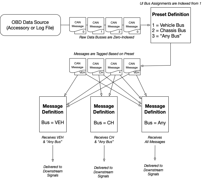
- The data source will often index each message received with a number, starting at zero (zero-indexed) In the tes•LAX user interface, these indexes will appear starting at one.
- tes•LAX will use the information in the active Preset’s page to convert the numeric tag to an actual bus name
- tes•LAX has the concept of an “Any Bus” messages sent to Any Bus will be delivered to all signals. Signals set to “Any Bus” will respond to any message regardless of how it is tagged.
- In the signal list, each message may be assigned to a specific bus name. Only messages from this bus, or “any bus” will be delivered to the message’s associated signals.
Side Note: Even if you are using a single-bus accessory, you may be able to use the “Location Augmentation” feature to synthesize signals on another bus using the iOS device’s internal GPS to provide location signals to certain visualizations.
Logical Diagram of Multi-Bus Message Flow
 Advanced: Filtering and JavaScript
Filtering
By default, tes•LAX will configure a connected OBDLink MX+ with filters to reduce the number of packets.
-
Upon connection, the messages needed by currently configured list of gauges across all pages and visualizations will be sent to the accessory for filtering.
-
When new gauges are added, the CAN bus monitoring will be temporary stopped to add add a new filter as needed.
-
When gauges are removed, the filtering will not be immediately removed. Instead, the app waits for buffer overrun. Before resuming monitoring, the filters will be cleared and reapplied with only the messages needed.
-
During logging, you can opt to disable filters. This is good for finding new messages in the logs, but you will experience repeated buffer overruns as the MX+ and bluetooth connection may not be able to keep up.
Buffer Overrun
By some estimates, some popular EV’s use 55-60% of the full 500Mbps of the CAN bus. The serial-based accessories then convert these messages to a more verbose, human readable hexadecimal format before sending the data over Bluetooth to your iOS device. This means that there is a lot of data going over the bluetooth link and often the connection can’t keep up. If the accessory supports the ST-command set, the app will ask the accessory to apply filters such that only the signals you are actively watching are being sent to the iOS device. With the default out-of-the-box view, you may have buffer overruns occasionally, but not repeatedly. You could reduce the number of signals on the display; but as you add more signals, you increase the bandwidth required and may exceed the capacity of the link.
When logging, you have the option to disable filters. As mentioned previously, you will receive repeated buffer overruns when operating in this mode.
When a buffer overrun occurs, the MX+ will temporarily stop monitoring the CAN bus. tes•LAX will re-provision the filters if necessary, and then begin monitoring again. This will result in a loss of some packets in the buffer and on the CAN bus until monitoring is restored. In practice, this may result in the some packet loss and a reduction of the refresh rate as you will not be able to receive every message that was transmitted on the CAN bus.
You can reduce buffer overruns by applying the following techniques:
- Reduce the number of gauges on your view. Specifically, you want to be monitoring fewer messages. Data transmission rates are not impacted by multiple gauges that monitor signals within the same message.
- Identify and avoid higher transmission rate signals in your visualizations. For example, some temperature signals are sent at a rate of once-per-second (1hz). Other vehicle controller messages are sent at a rate of 10hz. Craft your gauge selections to show you the data you’re interested and avoid unnecessary signals and messages.
- Make sure you have a strong, interference-free bluetooth connection to between your iOS device and your MX+ dongle.
JavaScript
For calculated signals, you can configure a bit of JavaScript. Here are a few notes:
Preset scripts
“Preset Scripts” are available in by editing the preset and selecting “Preset JavaScript”
- The ‘Initialization Script’ will execute when a Preset is made active. This is useful for initializing global state or loading libraries.
- The ‘Periodic Script’ will execute per the configured interval whenever a data source is streaming data.
Calculated Signals
Calculated signals execute and perform calculations on incoming CAN bus data.
-
Calculated signals are still associated with a message. They must be triggered by an incoming message to execute.
- All signals in the message are decoded and set as variables within the message. This can be used to create calculate signals from signals in the same message.
- All the bytes of the message are assigned as an array called message[] in the JavaScript context. This can be used to implement custom decoding.
-
Signals being used in the visualization are set as variables in the JavaScript context. If you wish to use a signal from another message, then you need to make sure it is part of your visualization somewhere else.
Examples
Battery Power
At the time of writing, one popular EV does not not have a BattPower signal. Instead, Message 0x132 has BattVoltage132 and SmoothBattCurrent132.
tes•LAX comes pre-configured with signal called “BattPower” which is a calculated signal with the following JavaScript:
BattVoltage132 * SmoothBattCurrent132 / 1000.0
Note also that this uses the “Kilowatt” unit type, so this signal will scale appropriately for both small and large values.
Average Cell Voltage
Not all products from a popular US EV automaker have a CAN bus message that shows individual cell voltages.
These are all part of one signal, and they come in multiplexed. This means each time the message is received it will have the voltages for a different set of cells.
In order to calculate an average across all cells, we need to average the CellVoltageXX_6F2 signals.
Since they come in over time, we need to check to see if they exist first (they may not yet have been seen)
This calculated signal is assigned to message 0x6F2 which contains the cell voltages. Every time a 0x6F2 comes in, the values are assigned to the javascript context. Over time all 96 will eventually be available.
function pad(num, size) {
    var s = num+"";
    while (s.length < size) s = "0" + s;
    return s;
}

var total = 0.0
var count = 0.0
for (cell = 1; cell <= 96; cell++) {
  var variable = "CellVoltage"+pad(cell,2)+"_6F2"
    var thisCell = null
    try {
        thisCell = eval(variable)
    } catch(err) {}

    if (thisCell != null) {
        count += 1.0
        total += thisCell
    }
}
total/count
In practice, you will see this signal fluctuate as cell voltages come in over time, until all 96 values are available.
This example also shows that you can have sub functions. (In this case, a quick-and-dirty function to zero-pad a number when determining the signal name)